Circuit Basics: What is a circuit?
Discover the fundamental components and configurations that make up every electrical circuit.
What is an Electric Circuit?
An electric circuit is simply a closed loop or path that an electric current can flow around. It consists of a power source (like a battery), and different components that use and manipulate the electricity. All of these different parts are connected together using wires .Every circuit boils down to these three things, so a good understanding is vitally important.
Voltage and Amperage: The Fundamentals
To truly understand circuits, you need to grasp the concepts of **Voltage** and **Amperage**. These two fundamental quantities describe the electrical energy and its flow within a circuit.
- Voltage (V): Often compared to water pressure in a pipe, voltage is the electrical potential difference between two points in a circuit. It’s the “push” or “force” that drives the electric current. The higher the voltage, the more potential energy each unit of charge has. Measured in Volts (V).
- Amperage (I): Also known as current, amperage is the rate of flow of electric charge. Continuing the water analogy, it’s the amount of water flowing through the pipe per unit of time. The higher the amperage, the more electrons are flowing past a point per second. Measured in Amperes (A).
Understanding these two concepts is crucial for comprehending how electricity behaves and how circuits function.
Key Circuit Components
Every circuit is built from basic components, each with a specific job. Learn about the most common ones and their functions.
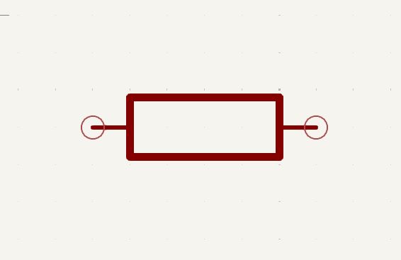
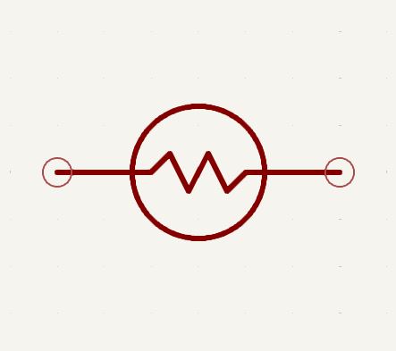
Resistor
Resistors oppose the flow of electric current. They are used to control current and voltage within a circuit. Measured in Ohms (Ω).

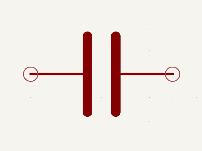
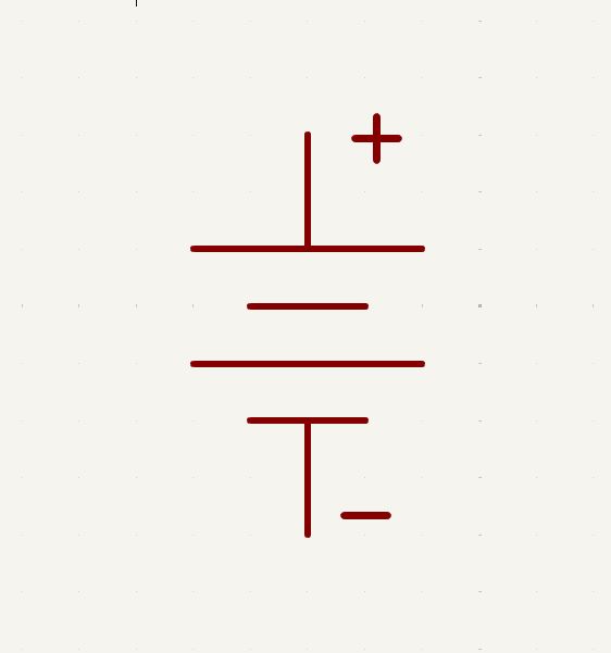
Capacitor
Capacitors store electrical energy in an electric field. They can block DC current while allowing AC current to pass. Measured in Farads (F).
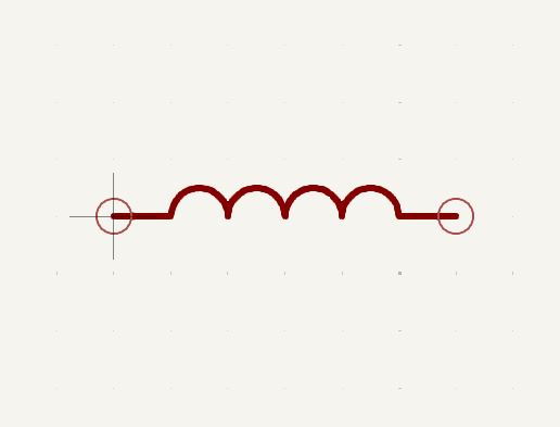
Inductor
Inductors store energy in a magnetic field when current flows through them. They resist changes in current. Measured in Henries (H).
Types of Circuits
Components can be arranged in different ways, leading to distinct circuit behaviors. Explore series and parallel configurations.
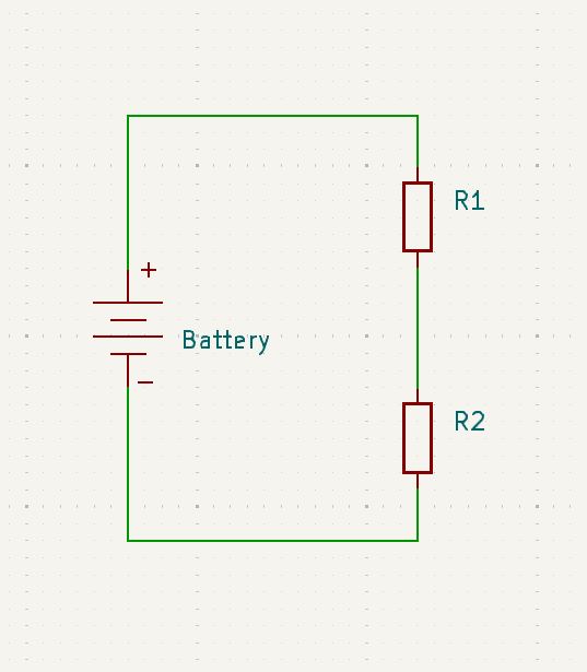
Series Circuits
In a series circuit, components are connected end-to-end, forming a single path for current to flow. The current is the same through each component, but the total voltage is divided among them. We explore this in more depth in lessons 2, and 3. in series circuits the different resistances are calculated by summing the resistances. Using the calculator bellow you can see how different resistance interact in a series circuit.
Total Resistance (R_total): — Ω
Total Current (I_total): — A
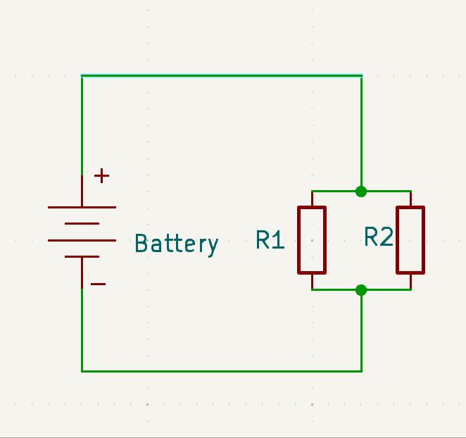
Parallel Circuits
In a parallel circuit, components are connected across the same two points, creating multiple paths for current. The voltage is the same across each component, but the total current is divided among the branches. One of the biggest advantages of wiring in parallel is that if one component fails the other ones will still work. The Resistance calculation is a little more complex, the resistances are calculated reciprocally, the calculation is as follows 1/Rtotal= (1/R1)+(1/R2)…..(1/Rn) use the calculator bellow to see how different resistances add in parallel
Total Resistance (R_total): — Ω
Total Current (I_total): — A
Series-Parallel Combinations
Many real-world circuits combine both series and parallel connections. To understand more complex circuits you typically need to break the circuit up into different sections. Luckily this is simpler than you might think, you can sum multiple resistors together then treat that equivalent as a single resistor (more information in lesson 4). By continuing this process through all components, and you can find the resistance of the total circuit. This methodical approach allows complex circuits to be broken down into manageable parts.
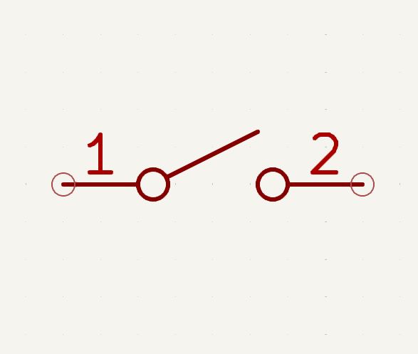
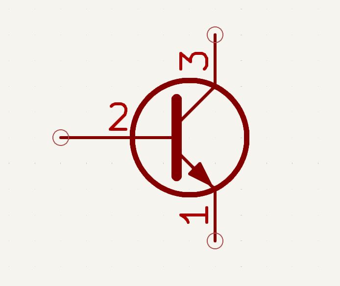
Reading Circuit Diagrams
Circuit diagrams use standardized symbols to represent components and their connections, making them a universal language for electronics.


Circuit States: Open, Closed, Short
Circuits can be in different states, each with important implications for current flow and safety.
-
✗
Open Circuit: This occurs when there’s a break anywhere in the circuit path. Current cannot flow because the path is incomplete. Think of a light switch in the “off” position.
-
✓
Closed Circuit: This is a complete, uninterrupted path from the power source, through the components, and back to the source. Current flows freely, and components like light bulbs will illuminate.
-
⚠
Short Circuit: A dangerous condition where an unintended, low-resistance path is created for current, bypassing the intended load. This results in very high current flow, which can cause overheating, fires, or damage to components and power sources.
Circuit Etiquette and Best Practices
Building and understanding circuits goes beyond just knowing components and calculations. There are common practices and conventions, often referred to as “circuit etiquette,” that ensure clarity, safety, and proper functionality.
-
Ground Reference: In many circuits, especially DC (Direct Current) circuits, the negative terminal of the power source is connected to “ground.” Ground serves as a common reference point for voltage and helps manage current paths safely. It’s often represented by the ground symbol (three horizontal lines decreasing in length) in diagrams.
-
Current Flow Direction: Traditionally, current is depicted as flowing from positive (+) to negative (-) in circuit diagrams (conventional current flow). While electrons actually flow from negative to positive, conventional current is widely used for analysis and design.
-
Component Orientation: Polarized components like diodes, electrolytic capacitors, and integrated circuits have a specific orientation. Connecting them backward can prevent the circuit from working or even damage the component. Always check datasheets and markings for correct polarity.
-
Clear Layout and Wiring: A neat and organized circuit, whether on a breadboard or PCB, is easier to debug and understand. Use appropriate wire lengths, color-coding (e.g., red for positive, black for ground), and proper soldering techniques.
-
Safety First: Always disconnect power before making changes to a circuit. Be aware of voltage levels and potential currents, especially in high-power applications. Use appropriate safety equipment and avoid touching live components.
Leave a Reply